
In preparation for new higher output solar panels expected to arrive later this month, it was time to upgrade our Blue Skies Cabin setup from a 12 volt to 24 volt system. When it comes to solar power the “system voltage” is dictated by the battery array. In our case we have been using a group of 12 volt batteries which meant we were using a “12 volt system”. As such our devices connected to this battery array had to be 12 volt devices. This includes the charge controller that is pushing solar panel energy into the batteries, the inverter that is converting the battery power from AC to DC voltage, and the accessories connected to our system including our monitoring battery shunt and the direct DC devices in our cabin such as our USB charger interface, the M One device, and other items like that.
This article covers some of the challenges we had in making this conversion and each element of our conversion process.
Disconnecting The Power
The first step was to disconnect everything. After putting on the protective rubber gloves, eye protection, and rubber soled sneakers it was time to get to work.
First thing was to disconnect the MC4 connector from our 800 watt solar array into the Rover 60 charge controller. Yes, we need to put in both the inline fuse and the disconnect switch but we haven’t gotten there yet. That will come when we upgrade our panels. For now it was using an MC4 disconnect tool (we prefer to use quality MC4 connectors and tools, with BougeRV being our current choice).
We then disconnected our battery array by taking the positive lead off our bus bar that connects our charge controller and inverter to the battery bank. We then did the same for the negative battery lead to the devices bus bar as we were going to redo some of the wiring for easy tracing in the future.
Lastly we disconnected the DC load output from the charge controller into the cabin.
The Batteries
It started with a decision months ago to go with (4) 12 volt LiFePO4 batteries with a future expectation that we would want to possibly upgrade to a 12 volt, 24 volt, or 48 volt system. An array of (4) 12 volt batteries makes all of those options possible by simply connecting the batteries in a different way.
Our original configuration was a simple set of 12 volt batteries each connected to a bus bar making up a 4 parallel (1S4P) set. This means the system was running at 12 volts with 4x the storage capacity. Since each LiFePO4 battery was rated at 300Ah we had 12 volts @ (4) * 300Ah = 1200 Ah of storage at 12 volts or 14,400 watt-hours (volts * amps = watts).
We re-routed wiring and in doing so ended up taking all connections off the bus bar and starting over. The batteries were rewired in pairs to create a 2 series, 2 parallel (2S2P) array. This is basically the same as creating two 24 volt batteries holding 300Ah each as wiring batteries in series increases the voltage but keeps the amps the same. Now we have 24 volts @ (2) * 300 Ah = 600 Ah of storage at 24 volts, meaning we still have 14,400 watt-hours but it is being pushed around our circuit at 24 volts now.
To create the 2S2P array we grouped the batteries into two sets, Set A and Set B.
Each set of batteries has a primary battery we will call A1 and B1 and a secondary battery named A2 and B2.
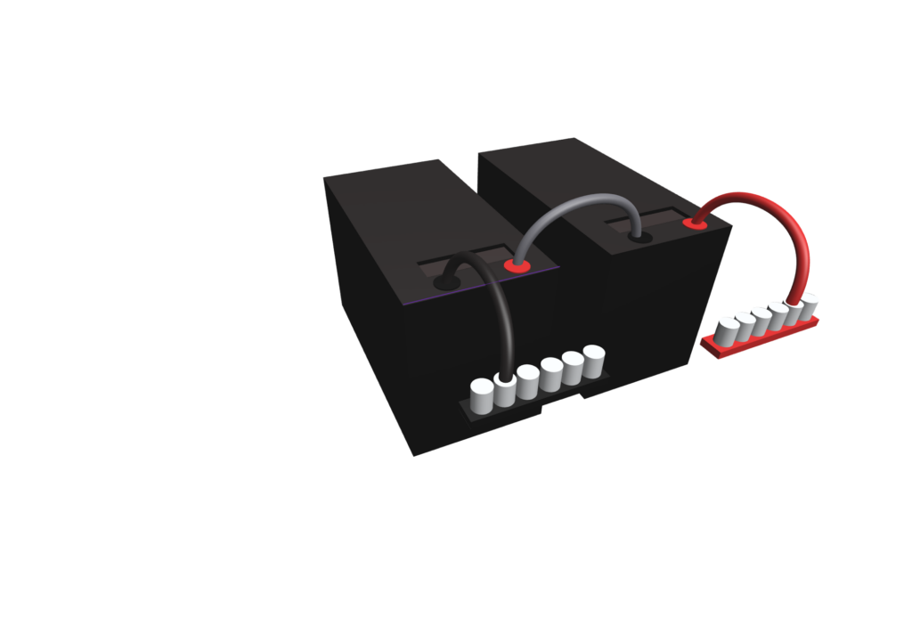
We connected the negative terminal of A1 to the positive terminal of A2.
We connected the negative terminal of B1 to the positive terminal of B2.
At this point we have basically created two 24 volt batteries with 300Ah of storage: Battery A and battery B.
We then connect the negative terminal of A2 to our negative battery bus bar. The bus bar helps distribute and consume power more evenly across the array.
We do the same with the “B” battery, connecting terminal B2 to our negative battery bus bar.
We then reconnect this negative battery bus bar to our Renogy 300 battery shunt (for better battery capacity tracking as the built-in BMS on our LiFePO4 batteries is cheap inaccurate garbage) and out the other side of that Renogy 300 to the negative equipment bus bar that our charge controller and inverter are connected to.
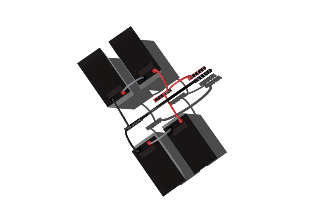
Now that the negative side of the battery array is connected we can start on the positive connection.
We connect the positive terminal of A1 to our positive battery bus bar.
We connect the positive terminal of B1 to our positive battery bus bar.
We then connect another positive cable from the battery bus bar through a new 200A DC breaker in the off position, and the other side of that breaker to our positive equipment bus bar (again where the charge controller and new inverter will go).
Note: This new 200A DC breaker provides and easy disconnect as well as an added protection measure in case our new inverter tries to draw too much power. It will not trip if the charger controller is forced to pull more than the rated 60A, we will deal with that later as well as adding a proper disconnect switch at several other points in the system to isolate components. Not a perfect design, but improved as we learn more through our DIY process.
The New Inverter
Unlike our Renogy Rover 60 charge controller which can be programmed to handle a 12, 24, 36, or 48 volt system (battery array) – the inverters we have been purchasing are a fixed setting. Our previous Renogy 2000W Pure Sine Wave inverter is only rated for 12 volts. Based on some research and finding a recommendation for Giandel brands on Will Prowse’s Mobile Solar site, we opted for the Giandel 3000W 24 volt inverter. Maybe we should have jumped straight to 48 volts, but the most cost effective options there are combined charge controllers/inverters and we are not ready to rip out and replace BOTH our perfectly good Renogy Charge Controller. We’ve already done that once before and will eventually repurpose our in-progress 24 volt kit and our pre-existing (first gen) 12 volt kit in the future. So for now, we only go from 12 volts to 24 volts by replacing one piece — our inverter.
The Renogy 2000W 12 volt inverter was disconnected from the component bus bar as well as from our hard-wired breaker box that supplies power through a TT30 outlet and 30 amp RV cable to the Blue Skies Cabin. We shut down the breakers, disconnected our DC side from the batteries and AC side hard-wired LNG connection from the inverter, then removed the grounding wire. Our Renogy 2000W will be re-united with the original 800Ah 12V AGM batteries and Renogy Rover 40 controller as a backup power source that it being trickle-charged with a single 100W panel. It will inherit our current 800W solar array later this month and power the Starlink this winter.
Now that the Renogy 2000W is offline, time to drop in our new Giandel 24 volt 3000W inverter. Despite taking some physical effort to relocate some wiring and the mount points due to the change in form factor (physical dimensions and layout) of this new controller, the connections were fairly simple. Having removed the Renogy battery bank cables to keep them with their original Renogy counterpart, we replaced them with the included battery bank cables from Giandel. Oddly the Giandel draws more power but comes with a smaller guage cable. Thankfully these are short runs and we don’t draw that much power, about 10 amps with our high efficiency heat pump. Also at 24 volts the cable resistance is overcome more easily and thus can get by with smaller gauge wires. That is one of the advantages of increasing voltage – longer cable runs over lower gauge wires due to higher efficiency and lower heat-loss. It is not quite twice as efficient, but it is an improvement.
We re-connected our grounding wire, the AC breaker box LNG wiring to our new 3000W 24 volt inverter, and then hooked up our negative and positive DC inputs to our component bus bars. We are just about ready to turn on the power and see what happens.
The Charge Controller
The charge controller only needed to be reconnected to our equipment bus bar due to some wire re-routing. We reconnected our charge controller to the equipment bus bar and were ready to turn things on.
Flick the switch on the new 200 amp breaker and the charge controller is now receiving power. It immediately starts throwing out an over-voltage alarm and shows a rapid white flashing light indicating an error. While it took a few tries to get this to reset, it eventually “took” the new settings. Here is what we had to do to program the Rover 60 to properly recognize our new 24 volt upgrade.
Scroll down from the main screen twice (first to load then parameters/SET) to settings using the down button on the controller.
Press the right button on the controller to enter settings.
Changing The Rover 60 Battery System Voltage
The first entry was reading for BattSysVol is “Auto”, which needs to be changed.
Press the right button to edit that setting.
Press the down button until 24V appears.
Press the right button to save that setting.
BattSysVol (the system voltage) should now read 24V.
Changing The Rover 60 Battery Capacity
From the BattSysVol setting, press the down button TWICE to skip over Battery Type since we are not changing our battery type – they are still lithium batteries just in a new configuration.
Capacity should be highlighted.
Press the right button to edit the capacity.
Press the down button to change the capacity to 600 as we now have 600Ah at 24V instead of the previous 1200Ah at 12V.
When the display reads 600, press the right arrow to save the setting.
You can now press the back button to exit out of settings and the up or down buttons to access the other screens.
Some notes on things that threw us off at first:
- The settings for things like battery voltages only show the 12 volt setting, WHICH IS SUPER CONFUSING IMO. Per the manual, you need to multiply that number (in your head apparently) by TWO for a 24 volt system (or 4 for a 48 volt) because that is how the controller will operate. For example:
- Over Voltage Disconnect will show something like 14.4 which is NOT correct for a 24 volt battery.
The controller actually DOUBLES that if your system voltage is set to 24, so it really means it will alarm and shut off over voltage at 28.8 volts.
Thanks Renogy for taking an extra hour to two writing the firmware code to do this math for us. - This applies to ALL battery voltage settings, charge limit voltage, equalize voltage, float voltage, low voltage, etc.
- Over Voltage Disconnect will show something like 14.4 which is NOT correct for a 24 volt battery.
- Even if you have Li battery type selected the settings will still show a equalize and float and other voltages WHICH ARE NOT ACTIVE (or should NOT BE) for Lithium batteries. <rant>Again, a failure on the part of Renogy to provide quality programming in their charge controller firmware. They really need to hire some real coders, because their coding “prowess” is lacking throughout their product line including the “One Portal” (garbage) and M One history tracking.</rant>
- For Lithium batteries they Equ-Time and Bst-Time is set to 0 minutes which essentially means those modes are disabled, which they should be. Why show a voltage for a setting that is not in use? Again… poor coding.
- The Over Voltage Alarm will not automatically clear after you change the system voltage.
- We ended up having to disconnect the Rover 60 from the battery array and the PV array after saving our settings , let it rest for a few minutes to entirely shut down, the reconnect everything before the error cleared.
- You SHOULD be able to long press while viewing the alarm/errors on the controller info page, but that did not work the first time.
- We also had to peform the complete power off / reset TWICE before the Rover 60 actually remembered our settings.
Reconnecting Our DC Loads In The Cabin
The last step of our 12 volt to 24 volt upgrade journey was reconnecting our in-cabin 12 volt loads.
One thing that is not documented ANYWHERE that we could find in the Renogy Rover 60 manuals or online specifications was WHAT IS THE DC LOAD VOLTAGE?
Is the voltage regulated? Or is this just a pass through directly from the battery, essentially having the Rover 60 load firmware switch act like a hard switch?
Turns out it is exactly that, a straight unregulated DC passthrough. We only found that answer by making sure everything was disconnected and using our voltmeter to check the line after the switch to a 24 volt system.
In our cabin the output from the Rover 60 comes in through a MC4 connector gland on the cabin into an automotive fuse bar rated for 12 to 48 volts DC power. The MC4 is hard wired to a positive and negative terminal with a dozen independent fused connections and terminals to attach our DC equipment. In our cabin we have a pair of 12 volt to USB-A connectors for charging up our USB lamps and other devices as well as running our Alexa pod. It also runs our composting toilet fan and most importantly our Renogy M One digital display so we can monitor our solar and battery power from inside the cabin.
Our new setup has the power coming into our DC fuse bar at just over 24 volts (expected for a fully charged 24 volt battery array). To rectify this we opted to put in a 24 volt to 12 volt DC converter. Our choice was a high quality Victron Orion-Tr 24 | 12-20 converter. Yes, Victron equipment is very expensive but since it is going inside our cedar-walled cabin the choice was to go for a trusted brand versus the typical chinese knock-off garbage for 1/4 the price. The extra money is worth it to not be worrying that the “eStink” (yes, a “REAL” chinese brand on Amazon) DC converter was going to burn the whole place down.
We disconnected the incoming DC line from the Rover 60 load output and re-wired that new 24 volt input into the input side of the Victron Orion-TR 24 | 12-20. We then used a new pair of moderate-gauge wiring to connect the output side, which is now 12 volts, to our existing fuse bar. Once everything was wired we could turn our Rover 60 DC output back on.
Side Note: In reality what happened was I forgot to turn OFF the DC load output after testing the voltage, and wired the Victron “hot” which of course shot sparks and immediately blew the 20-amp flat-blade fuse in the unit. Yeah, paying attention when doing this sort of thing is important. Thankfully there are plenty of fuses and other such accessories on hand at Rally Creek, so a few more trips to turn the right shit off, check connections, use a meter, and doing it RIGHT the second time was not a huge issue – just a reminder to work slowly and carefully even when doing just 12 or 24 volt wiring. Also – label shit properly, use RED WIRING FOR POSITIVE CONNECTIONS AND BLACK FOR NEGATIVE. Taking shortcuts and using generic non-colored wiring or the wrong color wiring could mean putting the positive lead into a negative terminal and poof – the magic blue smoke is released and you end up buying new equipment or possibly needing to test out the fire extinguisher. Thankfully there was no fire this time.
Why Go Through All This To Upgrade to 24 Volts?
After all this you may be wondering, why would we do all this just to upgrade our system from 12 to 24 volts?
Our total power storage is still only 14.4 kWh but now at 24 volts instead of 12 volts.
We incurred some minor losses on the DC side by adding a DC to DC converter from 24 volts to 12 volts, which is NOT as efficient as it could be.
Sure, a 24 volt system can be more efficient especially when it comes to resistance and heat loss through wiring, but that is negligible in a system like this. In theory the 24 volts inverter will incur less losses, but that may not be true as it also comes down to the quality of the components inside the inverter. A high quality 12 volt inverter can be MORE efficient than a low quality 24 volt inverter. To be honest, we never even check the efficiency ratings between the 12 volt Renogy and 24 volt Giandel (though Renogy I am guessing they are nearly identical as mid-range consumer products).
Sure the system is going to generate less heat in the wiring between components and that is a good thing for safety. We added some breakers and fuses, also a good thing for safety…. but the MAIN REASON for the upgrade comes down to the charge controller and the limitations set based on the system voltage.
For the Renogy Rover 60 running on a 12 volt system means we are maxed out with pushing 800 watts into the charge controller from the solar panels. By upgrading to a 24 volt system the Rover 60 can now double our input limits meaning we can double our solar array wattage. With new panels on the way for a couple of new projects we have planned for an upcoming EG4 48 volt system we will be able to swap our our eight 100 watt panels with 1600 watts on a set of 395 watt bifacial panels.
That means much faster recharging of our batteries to the point where even on a cold fall day the panels should be able to recover 80-90% of the energy we use overnight to heat Blue Skies Cabin and make our coffee in the morning. With our 800 watt setup our net usage on a cold fall night or hot summer day would leave us down 30% on our usable battery storage each night, meaning 3 cold or hot nights was our maximum time before we really had to start conserving power. When the new panels arrive it will be closer to a week or longer — and at Rally Creek there is rarely a stretch of cold (or hot) nights or cloudy days that last that long.